detour-build-guide
Detour - Build Guide
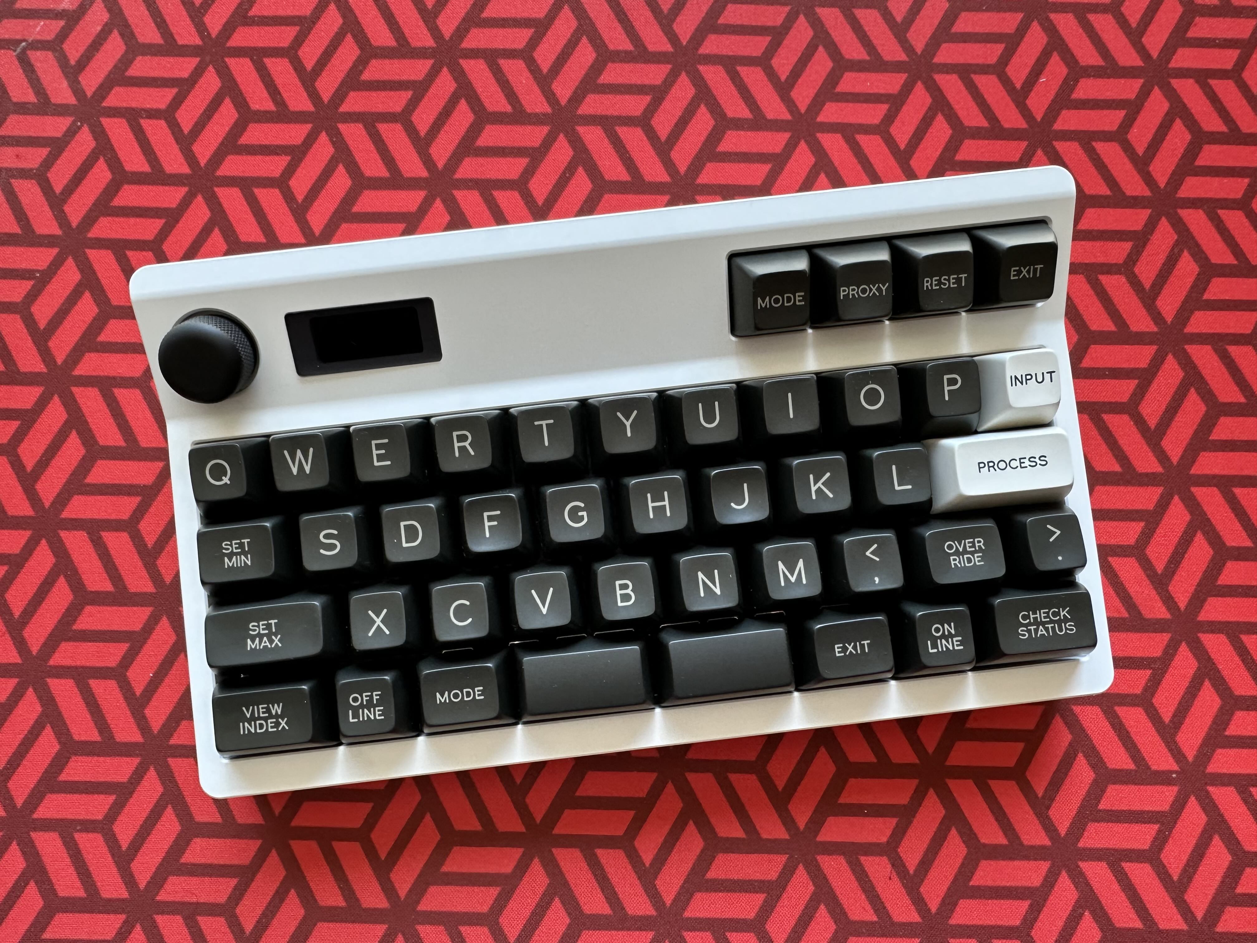
Detour is an 11u keyboard, designed by Nachie. The case features an 11u main cluster along with an angled macro row, rotary encoder and an OLED display. The main idea behind an 11u layout is having everything within reach from the homerow. There is little to no wrist moment needed to reach any of the keys. This is achieved by removing the number row and also some modifiers and symbol keys. These functions are obtained by using QMK features like tap-dance, mod tap and Homerow mods.
The case was heavily influenced from the Ave keyboard from TheRoyal. The keyboard supports a 11u layout which is a slight modification of the Vault35 layout from MechVault (which in turn was developed from the QAZ layout from tominabox1)
As of writting this guide, there was a prototype run of 5 units and an in-stock run from RNDKBD (units TBD).
Kit Contents:

Make sure you have the following before building.
- 1x Detour Case, top and bottom in aluminum
- 1x Syndrome PCB + Detour Extension (for macro row)
- 1x FFC Cable, UDB, UDB cable
- 1x Screw Pack for case and mounting
- 1x OLED and cover - Black Acrylic
- 1x Encoder Knob
- 4x Silicone Feet
- 1x FR4 universal plates for each, macro and main cluster
- 1x EC11 encoder
Macro Row Assembly
- Mount the macro row plate first. Only add screws on the top row.
- Add macro row switches onto plate.
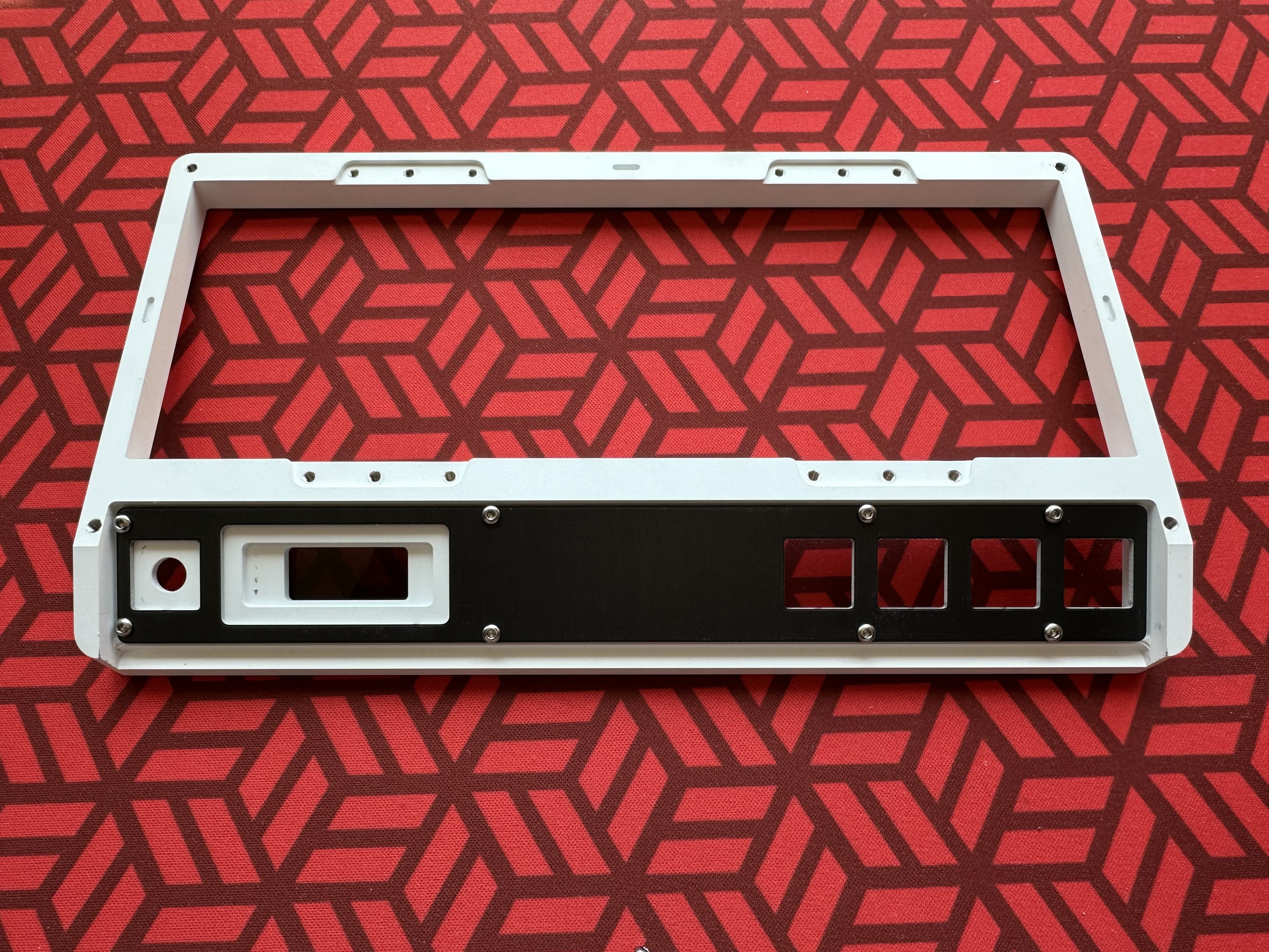
- Solder encoder onto macro row pcb.
- Solder pin header on OLED if not already soldered. You can use the included packing foam for keeping it level when you solder.
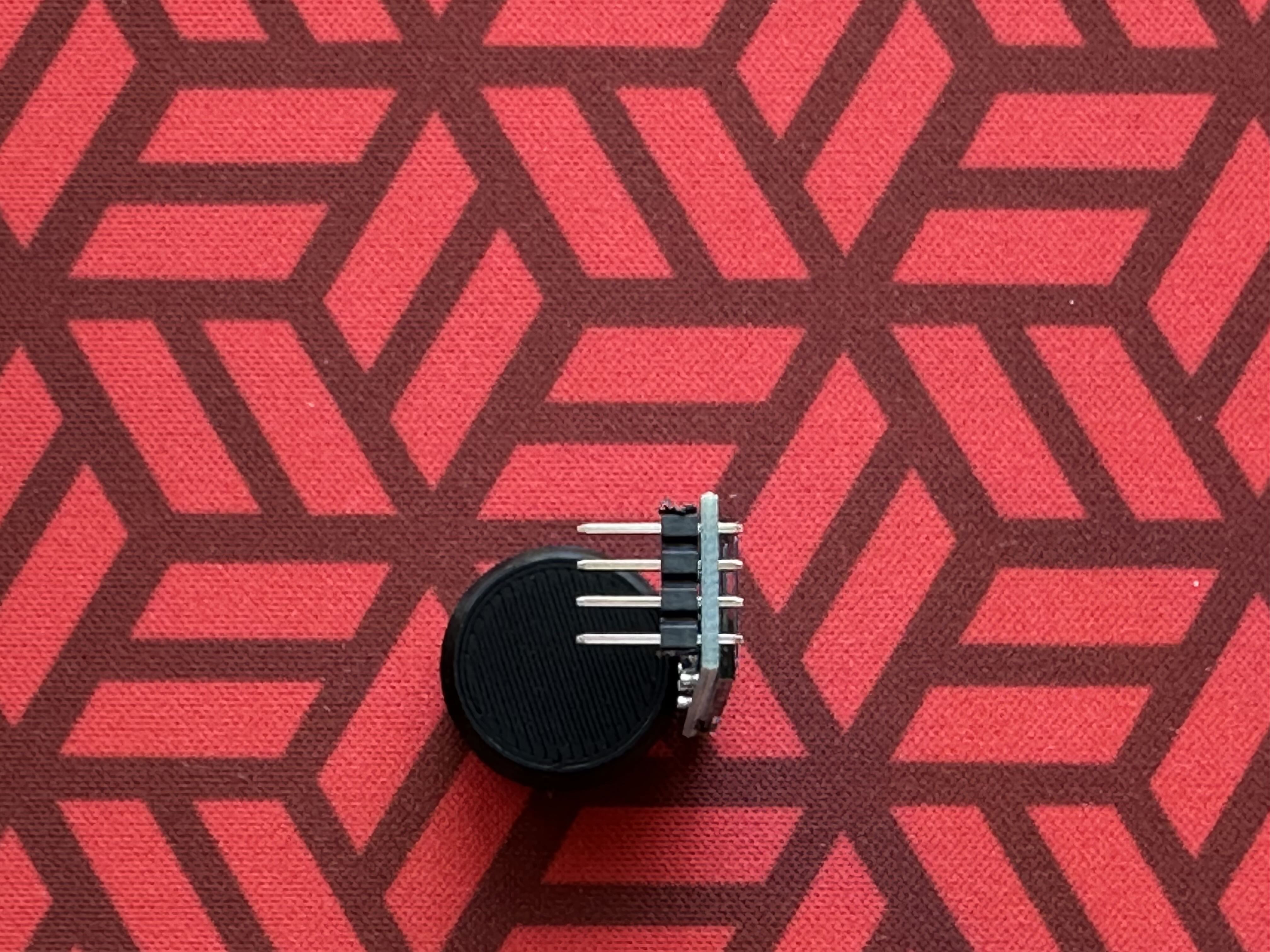
- Place OLED with header on pcb but don’t solder in yet.
- Place the pcb under the switches already mounted on the macro row plate and solder switches.
- Align the OLED by pushing down on pins so that the OLED lines up with the case inside, then keeping the case top upside down, solder the OLED pins. This ensures the OLED is aligned all the way to the case inside.
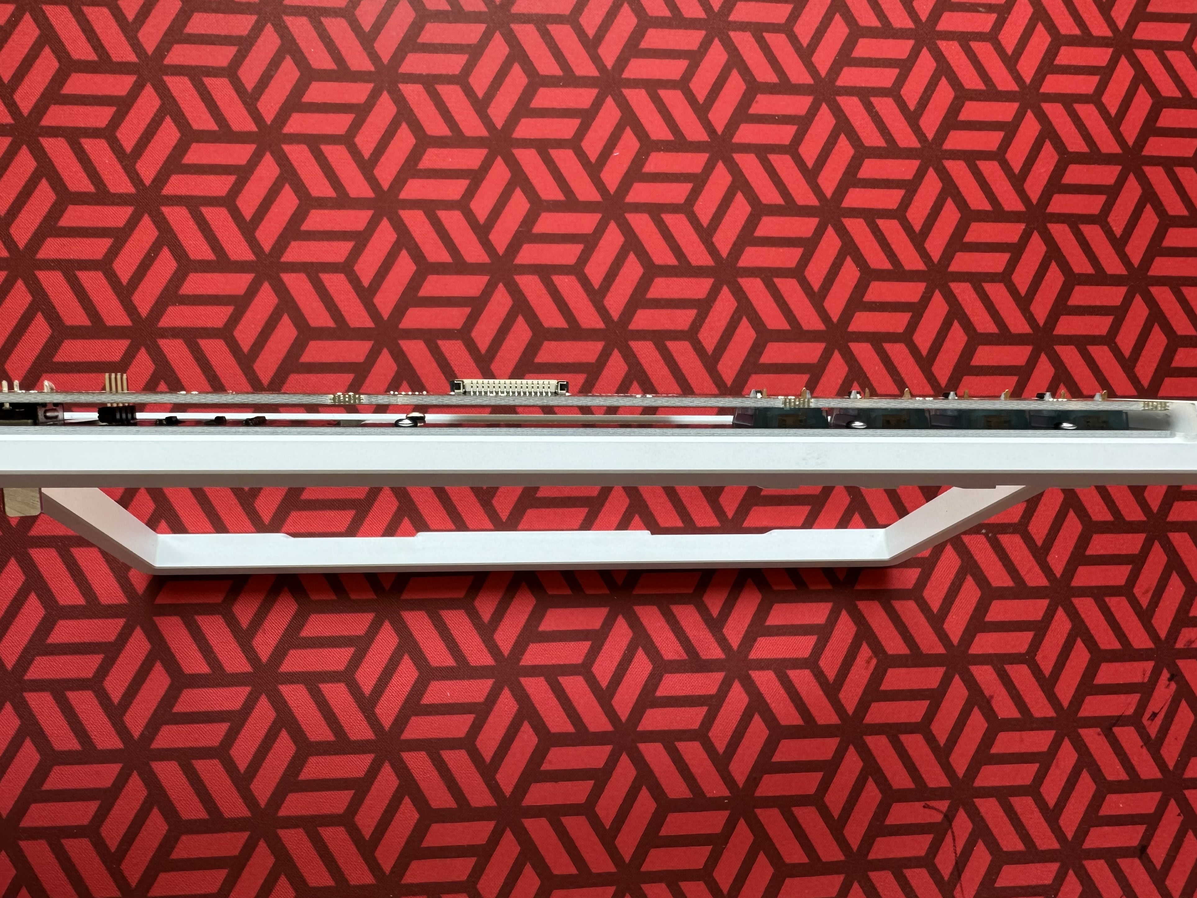
- Add mounting rings for encoder and screw it from the top of the case. If using a different encoder that doesn’t support screw mount, you may need to use the brass spacers provided to make sure the pcb is properly supported.

Universal Daughterboard (UDB)
- Mount UDB inside the case bottom, and attach cable.
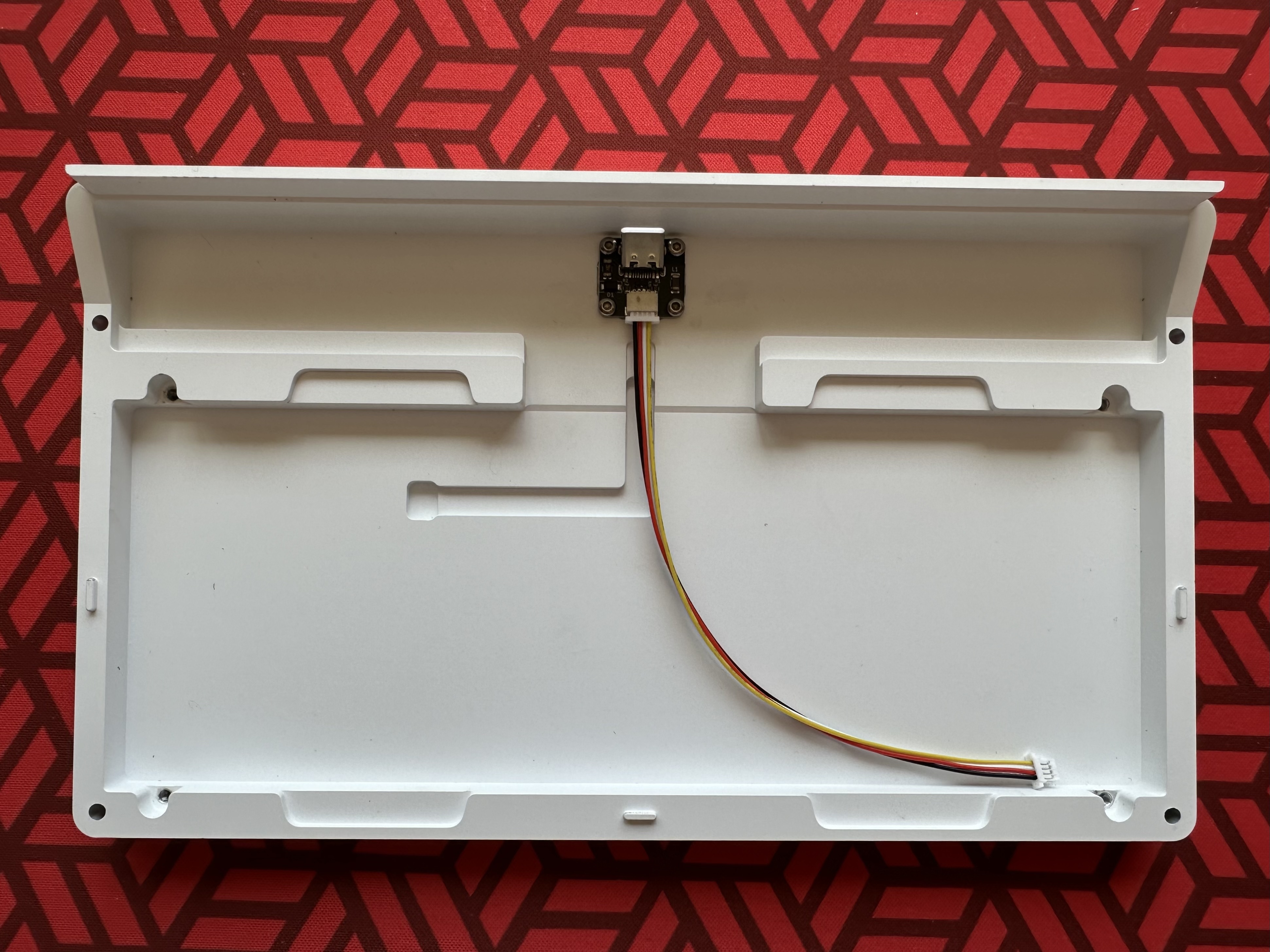
- Depending on C3 or C4, this would be the JST SH or EZ-Mate end of the cable respectively.
- The main cluster pcb only supports JST.
Choose mounting option
The Detour supports multiple mounting options.
PCB Mount
- For PCB mount, the plate is optional. Recommendation is to use 5 pin switches without plate.
- Tabs on PCB will be used for mounting it to the bottom case
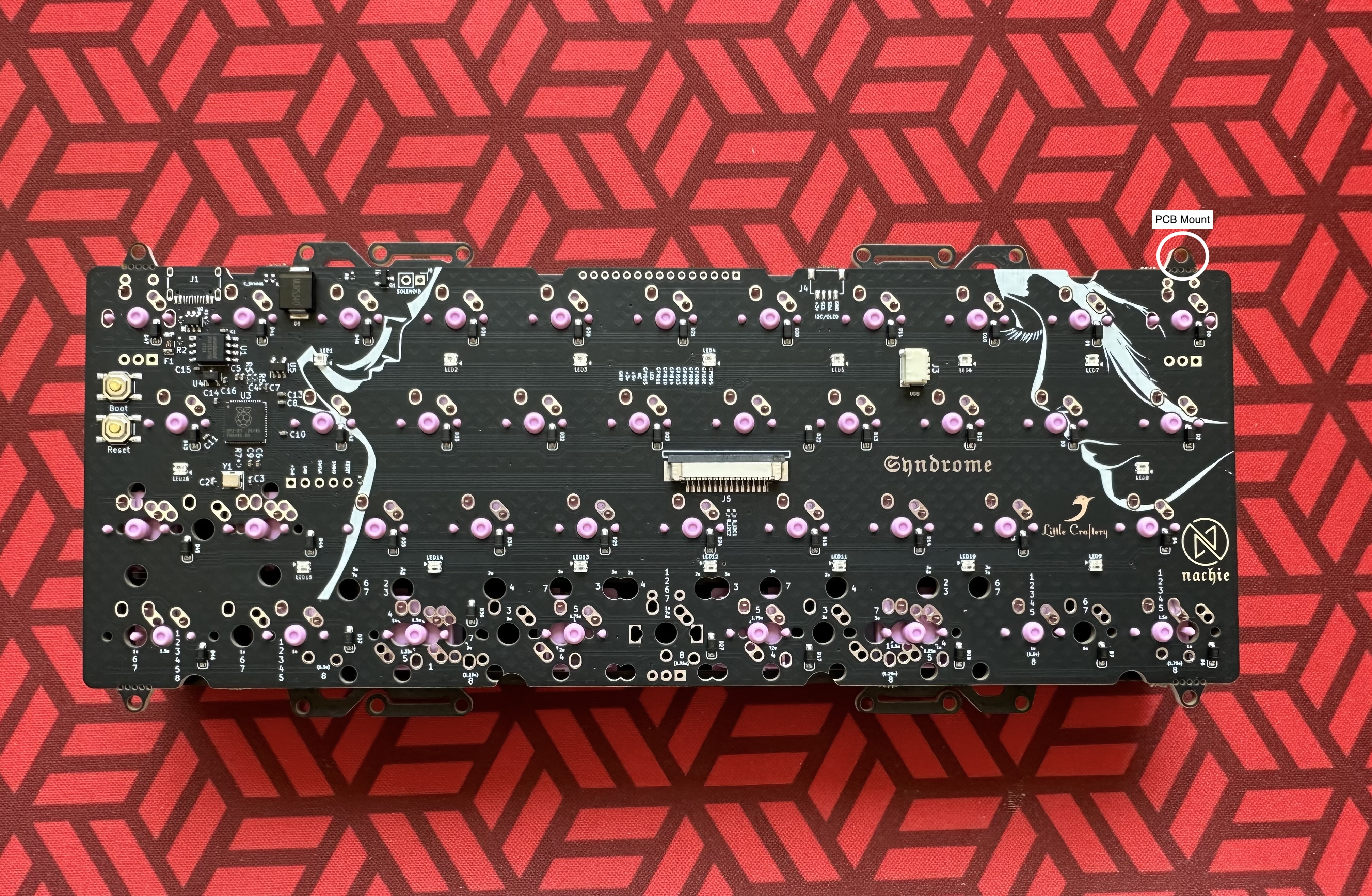
Top Mount/Leaf Spring
- The Detour uses Syndrome Plates. These plates provide custom modified LeafSpring mounting tabs with three mounting locations IMG-Plate tabs
- Using the center holes on the tabs provides leaf spring mount, this is the flexiest.
- Using the inner most holes on the tabs essentially make it a bottom mount.
- If you want an in-between, use the outermost holes on the tabs.
- Optional: Use o-rings between plate and case for even more sound dampening or flexer leaf spring action.
- Optional: Break of pcb tabs if not doing pcb-mount. This is irreversable but recommended for the ideal build.
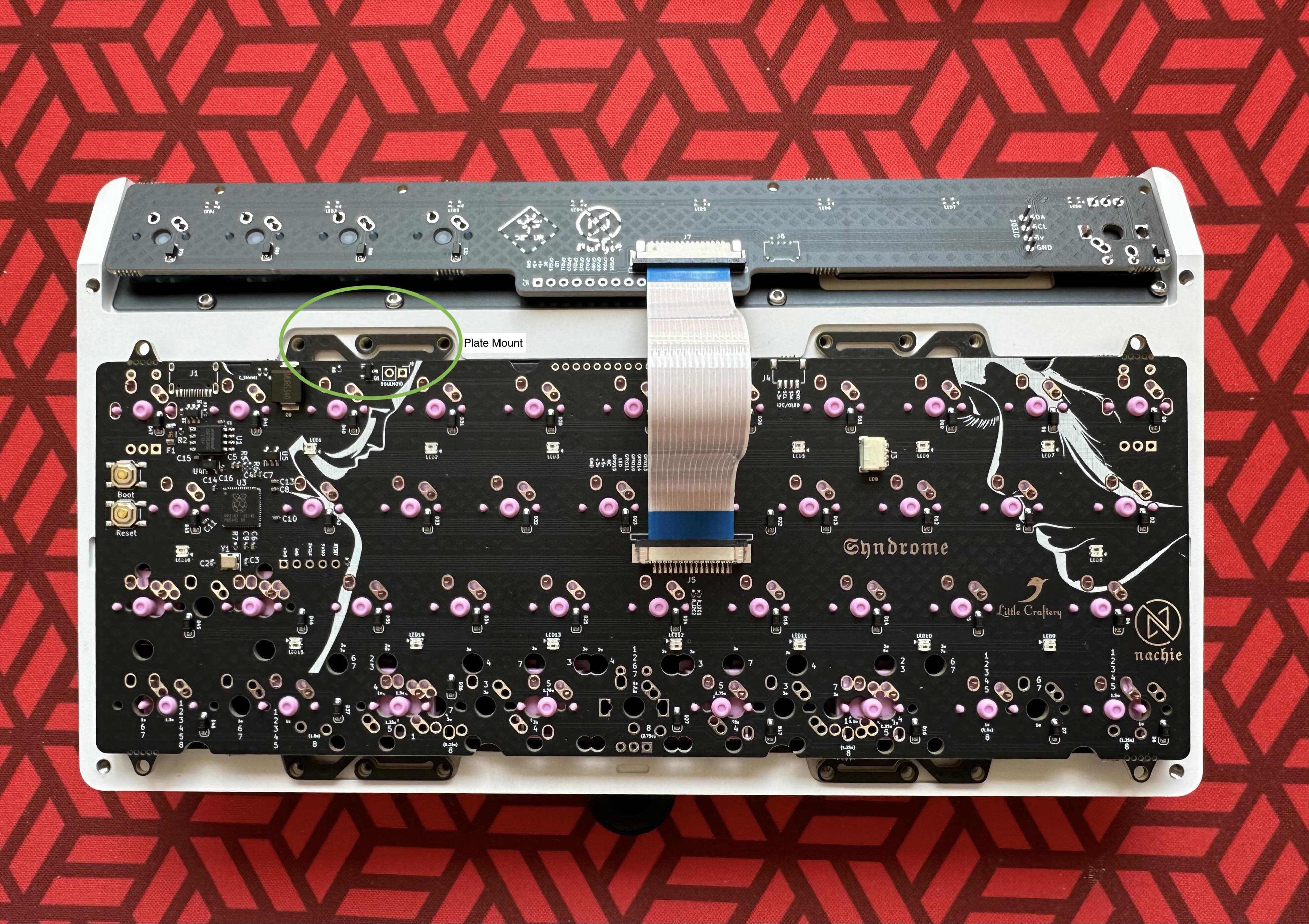
Main Cluster Assembly
- If using a plate, add desired switches to the plate. Otherwise mount the switches on the pcb. Solder as usual, nothing special about this part of the build.
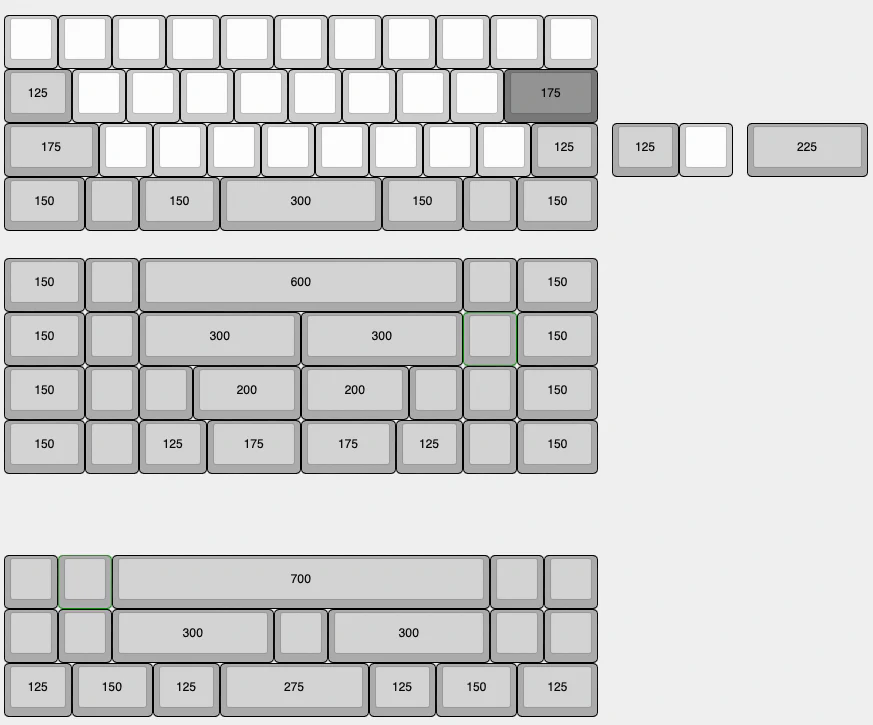
- Using keycaps can help in figuring out where to place switches for the bottom row.
- Syndrome PCB for the production run also has silkscreen that shows switch and stab locations for the bottom row, the numbers indicate the bottom row option on KLE.
- Once the main cluster is soldered and ready, add the FCC cable by first pulling out the black tab on the connector on PCB, inserting cable and pushing the black tab back in to hold it in place. Blue tape on the cable faced away from the pcb.
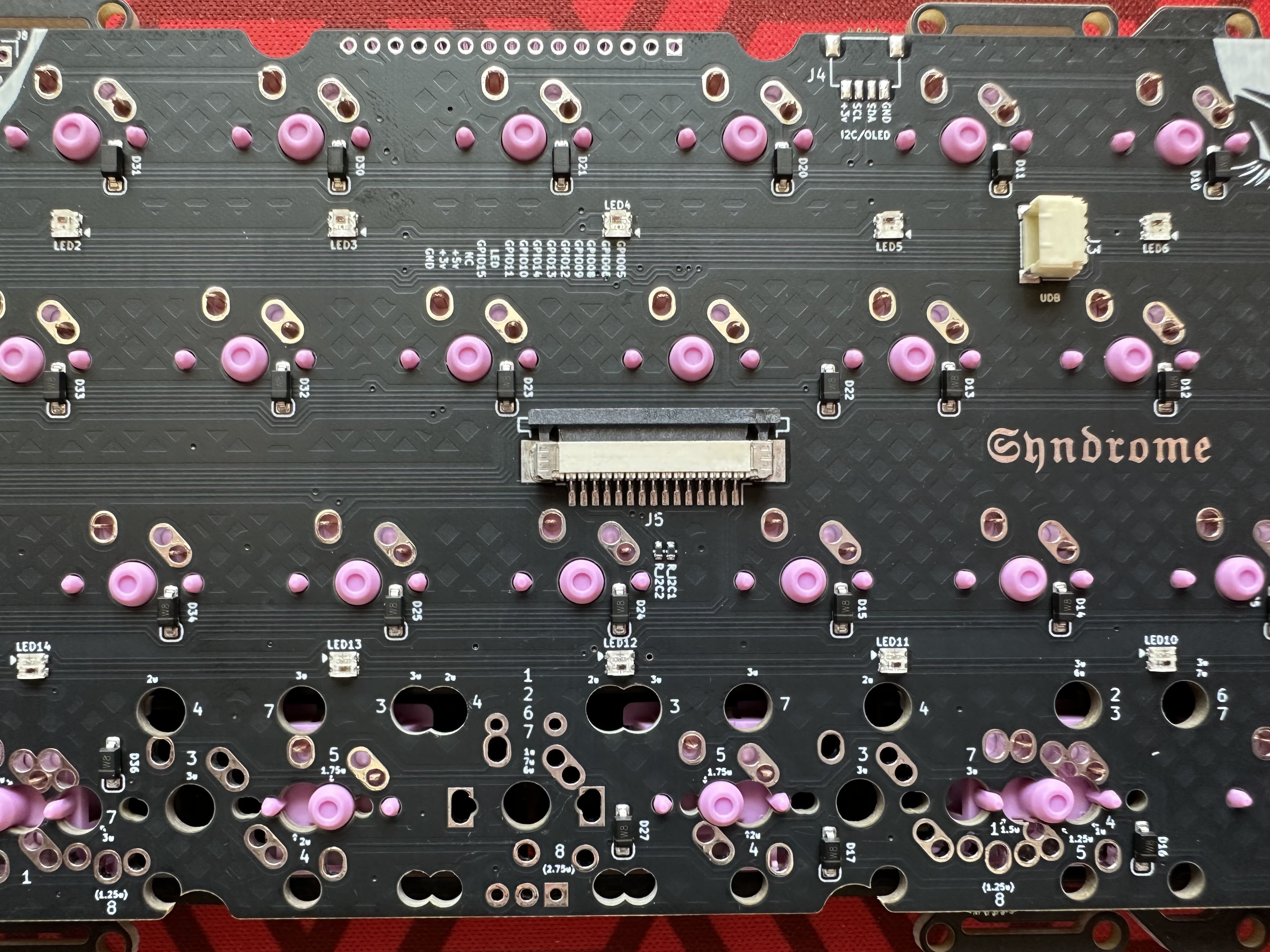
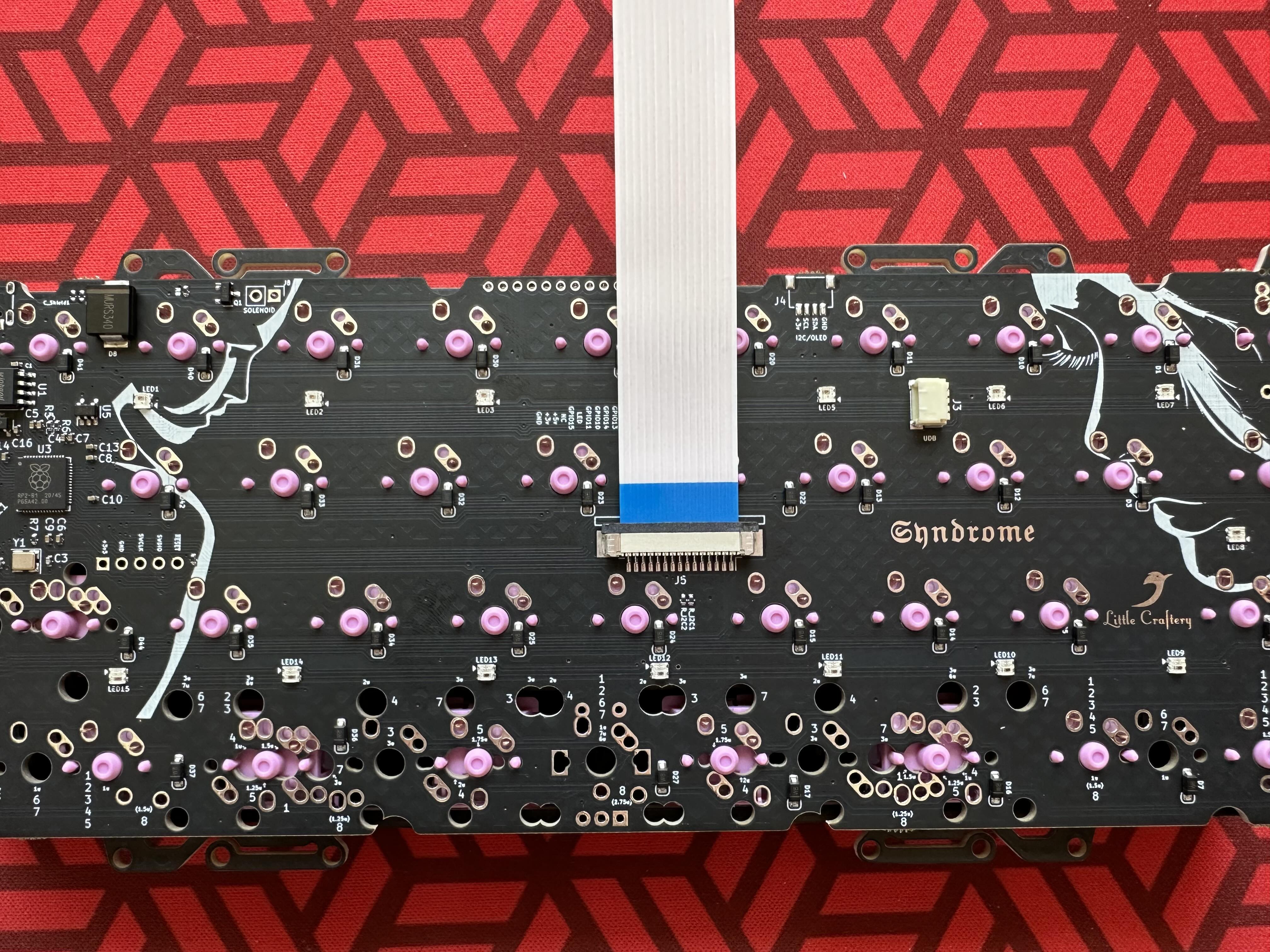
- Attach UDB cable to PCB and test it out. PCB should be flashed with vial and show up on the interface.
Piecing it together
Now is the bit due to which you are probably reading this guide in the first place. It isn’t complex, but does requires some co-ordination and maybe there is a better workflow here, but here is the recommended way.
- The main cluster should be screwed in at this point with UDB attached to it and tested.
- The main cluster should have the other end of the FCC cable unconnected.
- The top case should have the macro row assembly soldered and screwed in place.
- Place the main cluster assembly on top piece of the case. Encoder knob underneath can help hold the piece flat.
- Pull out the black tab on the connector.
- Blue side away from pcb, push the cable and push down on the black tabs to hold it in place.
- Also make sure the cable is pushed all the way in before locking the tab.
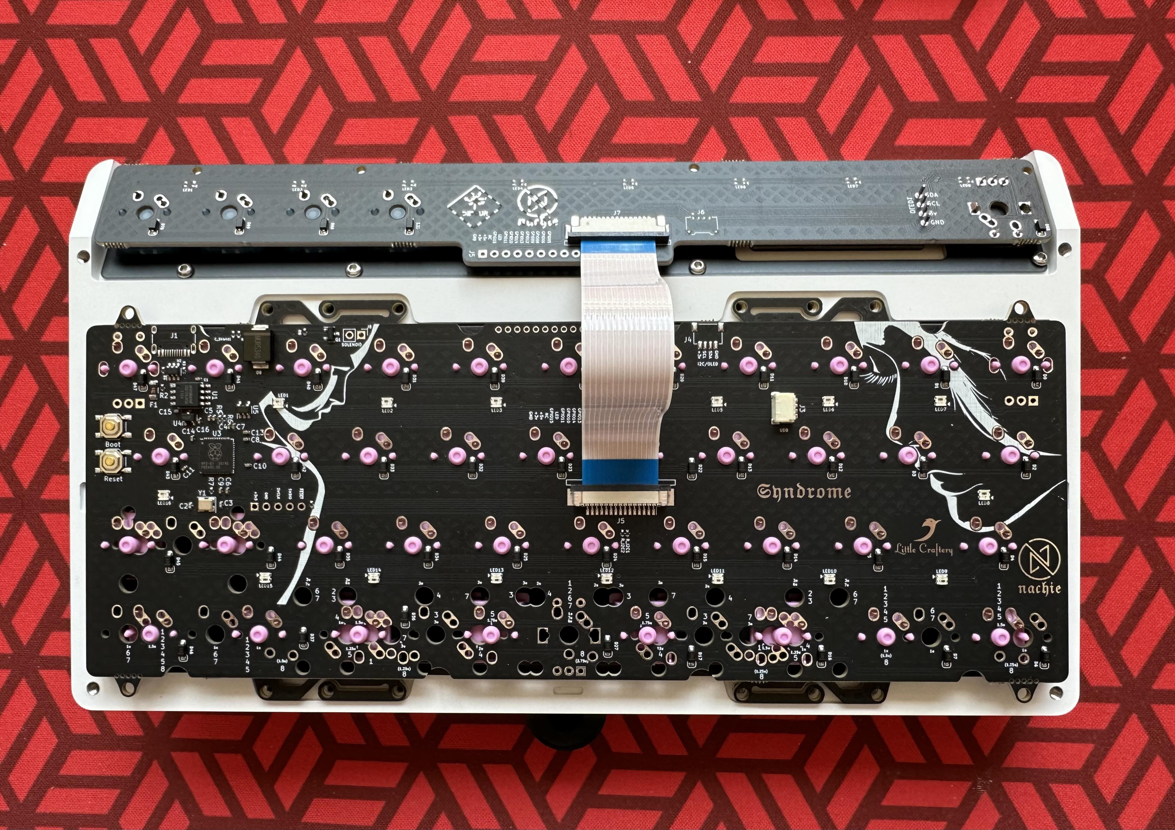
- Tuck the FFC cable down a bit, this helps in closing the case later.
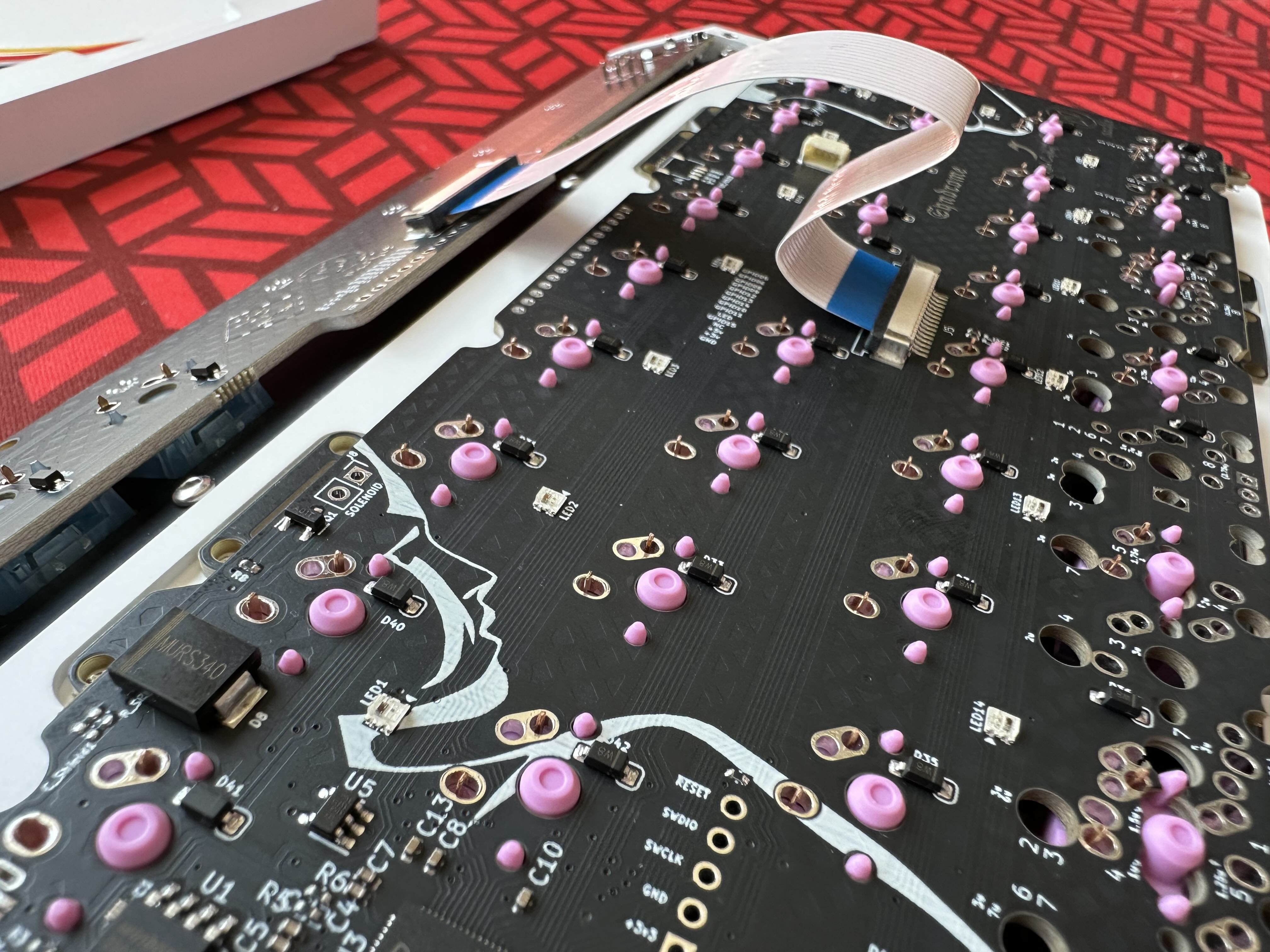
- If doing Plate Mount, add screws to the plate. If doing PCB mount skip this step.
- Tip: For the next part, use some paper in between top and bottom case to avoid scratching the pieces if they rub together.
- Hold the top piece close to the bottom and attach JST Cable.
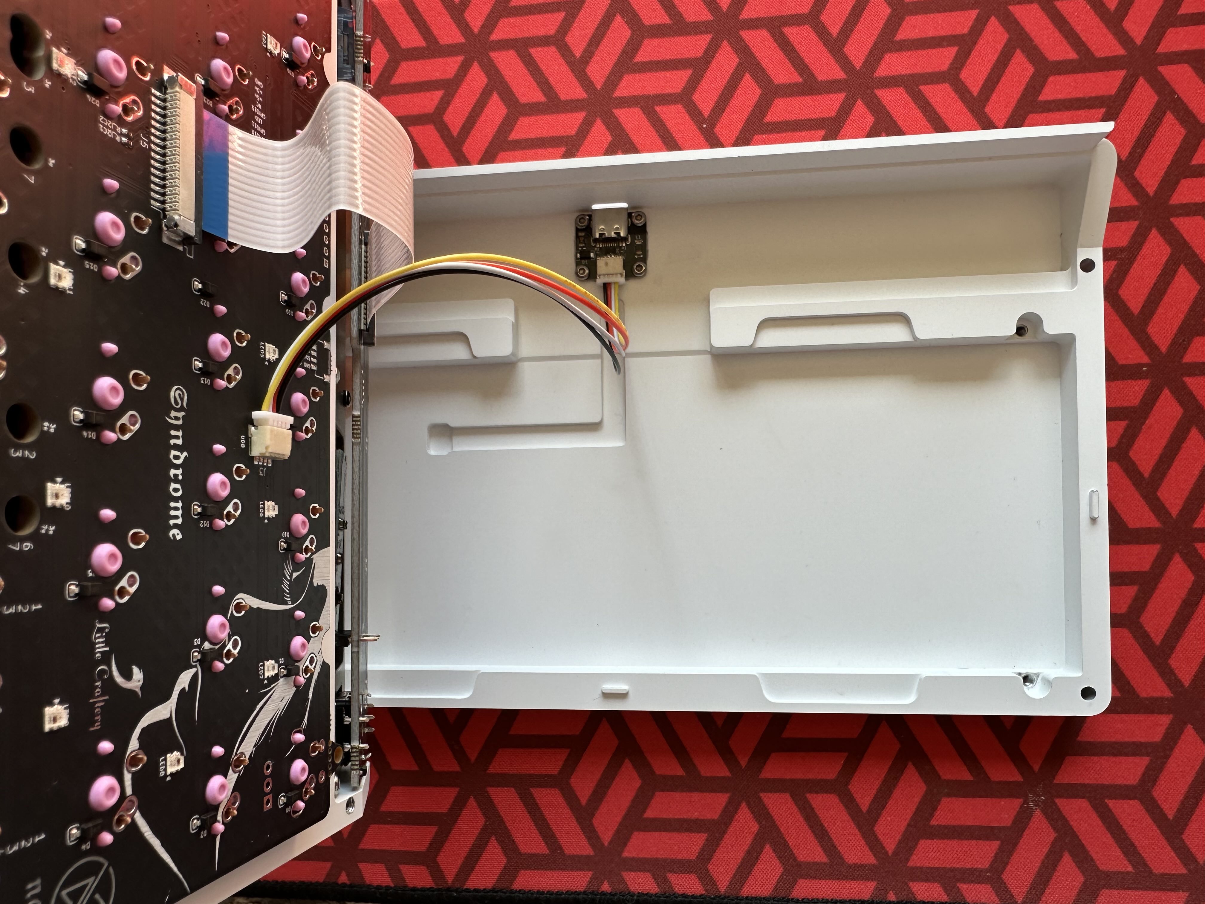
- If doing a PCB mount, let the assembly fall into the bottom case, plate top case with FFC attached on top, or hold with one hand. Add pcb mount screws into bottom case.
- Close the top and bottom, use alignment pins to align, close slowly so as to not damage any cable.
- Add provided M3 screws to screw case together.
- Add silicone feet in the machined grooves.
- Use the included adhesive strips to add in the OLED cover. On prototype units, the cover and feet came attached by default.
- Connect the board, make sure all keys register. Some keys on the default keycap are layer keys, so testing in vial is recommended.
Troubleshooting
If you run across any issues, please re-read the relevant section here to see if it can be resolved. If not, reach out over discord on the 40s #detour channel or RNDKBD discord.